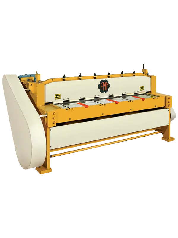
FMT® Brand Steel Body Geared & Ungeared Power Operated Shearing Machines are designed for parallel sheet cutting. The machine is applicable to M.S., S.S., Copper, Brass, Aluminum, CRC, G.P./M.G.O., P.S.E., etc. cutting industries. It is also applicable to manufacturers of Electric Stampings, Automobiles, Tin Drum Barrel, Control Panels and Board, Steel Furniture, Tube Light Poles, Fabricators, and Kitchenware items, etc.
Side Frames: Made of steel plates designed for maximum rigidity to eliminate deflection and vibration and withstand continuous high-speed performance at full capacity.
Ram (Upper Beam): Made of solid steel plates with additional ribs on the back side for added strength, carrying the upper knife. Its maximum weight ensures lesser load on the bearing. There are no moves in accurate machined guideways to avoid deflection, ensuring smooth running and maintaining the proper strength of the upper knife.
Table: Use of close-fitting steel fabricated structure forms a rigid back-bone for the front shear and a solid backing for the lower knife. Additional ribs under the table add to its strength.
Blade: Is of superior HCHCr, polished for longer tool life.
Crank Shaft & Flywheel Shaft: High-tensile steel shafts are accurately machined and run in gun metal bearings and all other installed in gun metal bearings.
Hold Down: Is of steel fabricated spring-loaded levers uniform pressure throughout the cutting length without any slipping respective to the sheet.
Rolling Key Clutch: Made of EN-24 steel for positive engagements and continuous operation having three keyways. Single rolling key systems are incorporated in the machine, ensuring easy and efficient working of the machine.
Drive: Through V-belts driven by the motor and chain of job cut gears for smooth running and longer life.
Brake: Consistently applied adjustable brakes provided.
Back Gauge: Fitted in FUS 4.6, FUS 5.6, FUS 7.0, etc., screw drive versions in FUS 10.4 & FUS 13.0 are of rack and pinion type designed to accuracy and easily.
Lubrication: For sufficient lubrication, oil cups and oil points are provided.
Standard Equipments: Side back, front gauges, table extension, flywheel, and gear guards, foot pedal, mount and motor pulley, hold-down divide, set of 4 edge HCHCr blade and manual oil pump for lubrication.